|
Frequently Asked Questions
The information provided by this response is intended for reference purposes only, and neither SEAOSC nor its committees or individuals who have contributed to the responses make any warranty, expressed or implied, or assume any legal liability or responsibility for the use, application of, and/or reference to opinions, findings, conclusions, or recommendations provided. The information provided should not be used for any specific application without competent examination and verification of its accuracy, suitability, and applicability by qualified professionals. Users of information provided in FAQ responses assume liability arising from such use.
Do you have other questions about one of your projects, a Code interpretation, or anything Structural Engineering related? The SEAOSC committees, Board, and expert members are here to help.
Category: Structural Design
Answer: Currently there is no code provision in ASCE 7 specifying an inter-story drift threshold below which the designer is not required to provide drift joints. Proper connection of exterior finishes to the structure considering the effects of seismic drifts may be adequate to mitigate life safety concerns, but cracking and local spalling of stucco finishes can remain as a serviceability consideration. There is an on-going discussion on this topic among the SEAOSC steel committee members as well as the industry at large. The SEAOSC Steel Committee is currently developing a statement that touches on the different factors that should be considered when addressing story drift. These include cladding material, recent and relevant research, and local projects that have been analyzed.
Some useful references that may be helpful for your purpose include AISC Design Guide #3 - Serviceability Design Considerations for Steel Buildings ( https://www.aisc.org/products/publication/design-guide/design-guide-3-serviceability-design-considerations-for-steel-buildings-second-edition/) which discusses serviceability considerations and FEMA E-74 Reducing the Risks of Nonstructural Earthquake Damage (free download at https://www.fema.gov/emergency-managers/risk-management/earthquake/training/fema-e-74) which discusses how potential falling hazards may be mitigated.
As a SEAOSC member, you are also welcome to participate in the ongoing Steel Committee discussions on this topic and provide your input at the committee meetings. SEAOSC Steel Committee typically meets the last Thursday of the Month, virtually. If you are interested in attending a meeting or joining the Steel Committee, please email the committee chair(s) at steel@seaosc.org.
Answer: There are a few different options that may be considered when designing these connections at re-entrant corners. The specific details of each project should be taken into consideration when determining which option is best.
1) Design a steel ledger along the length of wall 2 with slotted holes so that it releases in-plane movement in the E-W direction. In this case, the diaphragm would be designed to span between walls 1 and 3 for E-W seismic loading. Note that the ledger connection must still provide out-of-plane restraint for wall 2. It should be noted that the roofing over this area may be compromised due to movement in a seismic event.
2) Design a drag element and connection to collect and transfer the tributary area load into wall 2 for E-W seismic loading. Design of the drag element and its connection to the wall shall use load combinations with the Overstrength Factor per ASCE 7-16 Section 12.4.3. Wall 2 must be designed for the tributary lateral load in accordance with all relevant seismic design provisions of ACI 318. This may be particularly difficult to achieve when wall 2 is very short and the tributary area is very large.
3) Design a drag element and connection at the re-entrant corner to collect and transfer into wall 2 a load equal to the maximum capacity of wall 2 as a participating shear wall or as a rocking wall. In this case, the drag element and connection need not be designed for Overstrength level loads, but the difference between the tributary area load and the capacity of wall 2 must be carried by the diaphragm spanning between wall 1 and wall 3. Careful consideration must be given to the detailing of the wall and its various connections such that the intended behavior will be achieved and the associated deformations can occur without loss of the building’s gravity load carrying strength.
Additional considerations and guidance regarding re-entrant corners specifically in concrete tilt-up wall buildings can be found in the 2019 SEAOC bluebook Article 09.02.010 (https://www.seaoc.org/store/viewproduct.aspx?id=14896296).
Category: City of Los Angeles Nonductile Concrete Retrofit Ordinance
Additional disclaimer: The responses to the following Los Angeles Non-Ductile Concrete Ordinance 183893 (referred here as the LA NDC Ordinance) questions are based on the opinion of the SEAOSC EBC and may not represent the views of the City of Los Angeles. The Engineer of Record of any given project is solely responsible for confirming the response to these questions with the City of Los Angeles Department of Building and Safety (LADBS).
Answer: The version of referenced standards for the LA NDC Ordinance, such as ASCE 7 and ASCE 41, is the version referenced in the current Los Angeles Building Code (LABC). A different version may be accepted by applying for a modification.
Answer: Limitations to structural systems applicable to new buildings do not apply to existing buildings for existing structural systems or systems used to retrofit existing buildings. However, if using ASCE 7 for retrofit, the system used to retrofit must meet the detailing requirements of that system.
Answer: If using ASCE 7, the retrofit must eliminate the prohibited irregularity. If using ASCE 7 or ASCE 41 non-prohibited irregularities must not be made worse.
Answer:
1. Existing as-built drawings.
2. Material Testing Program and Condition Assessment.
3. Drawings: In addition to the structural drawings, architectural and MEP drawings shall be included showing the ADA scope.
4. Structural calculation package.
Answer: Materials used to protect the element with the FRP must comply with LABC Section 703.2 or 703.3. Fire rating for FRP is only required if the element in question carries gravity loading and would be unable to maintain gravity load-carrying capacity if the FRP is considered completely in-effective. However, it is strongly recommended that the engineer review specific FRP applications with the City prior to making any decisions as to whether fire rating is required or not.
Answer: Disabled access upgrades are required by Chapters 11A or 11B of the Los Angeles Building Code (Title 24 of the California Code of Regulations).
Answer: Compliance with the LA NDC Ordinance will not inherently require fire life safety upgrades. However, Section 8604 of the LABC includes fire safety standards required for existing buildings. Buildings that have been issued an Order to Comply with the fire safety standards and that will be occupied above the first story will need to demonstrate compliance with the fire safety standards of LABC Section 8604.
Answer: No. As long as there is not a vertical load-bearing non-ductile concrete element supporting a concrete floor, the building is not included in the ordinance.
Answer: Where portions of the building meet the definition, the entire building is affected by the non-ductile concrete retrofit ordinance and the entire building must comply with the requirements of the non-ductile concrete retrofit ordinance.
Category: Concrete
Answer: While designing anchors for seismic forces in SDC C-F, one must satisfy ACI 318 ductility criteria (ACI 318-14 section 17.2.3.4.3 or ACI 318-19 section 17.10.5.3). To simplify:
Satisfy condition (a): Design a ductile anchorage where ductile failure governs. This means steel failure occurs before brittle failure. Brittle failure includes concrete breakout or pullout.
Or
Satisfy condition (d): Design anchorage with omega overstrength factor (i.e., multiply the design load with applicable omega). There is no need to design for ductility with omega factor because the anchor system is designed to behave linear elastic.
Answer: In the Chapter 17 anchor provisions, the design strength is based on ultimate strength of anchors (threaded rod or rebar.) Embedment is limited to 20 times the diameter of anchors.
In the Chapter 25 Rebar Development Length provisions (RDL), the design strength is based on yield strength of rebar, limited by the rebar. Embedment is limited to 60 times the diameter of rebar. The provisions determine the embedment required to develop the yield strength of the rebar, which is the embedment depth such that the yield strength of the rebar is developed before concrete splits or the rebar pulls out of the concrete. RDL provisions are very helpful for applications that need deeper embedment, since the anchor provisions are limited to 20 times the diameter of the anchor. Since the RDL equation (copied below) requires a minimum of 12” embedment, it is limited to applications that can accommodate deeper embedment.
%20v%20Rebar%20Development%20Length%20(RDL)%20Provision%20(ACI%20318-14%20Chapter%2025).png)
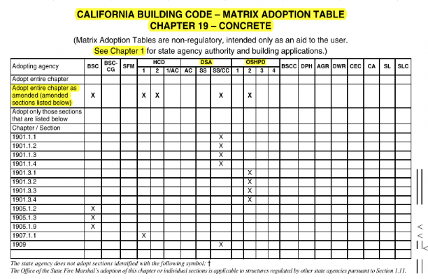
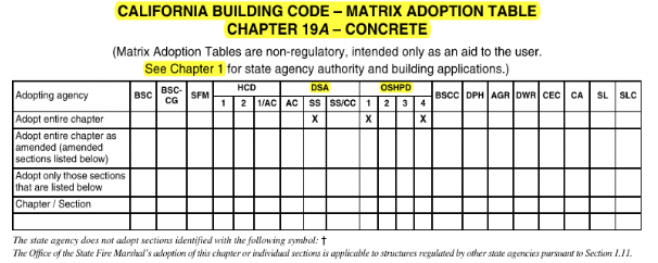
Answer: Proof loading is generally done to determine the soundness of the anchor installation. Proof loading requirements shall be shown on the construction documents for DSA and HCAI (HCAI was formerly OSHPD). For non-DSA/non-HCAI projects, there is no proof loading requirement specified in the CBC. The EOR may assess the life safety of the application and provide proof loading guidelines. DSA/HCAI guidelines below may be helpful in establishing proof loading guidelines. Refer to CBC section 1901.3.4 for HCAI and section 1909.2.7 for DSA guidelines. Refer to CBC Chapter 19A (section 1910A) for DSA-SS and OSHPD1/OSHPD4 requirements. Refer to CBC matrix adoption table (see below) for the code section information.


Test load (CBC section 1901.3.4.4 for HCAI and CBC section 1909.2.7.4 for DSA): Tension test load is to be twice the maximum allowable tension load or 1-1/4 times the maximum design strength of anchors, with the tension test load not to exceed 80% of the yield strength of the anchor. HCAI exception: Torque-controlled post installed anchors shall be permitted to be torque-tested. DSA exception: Torque-controlled post installed anchors and screw anchors shall be permitted to be torque-tested.
Test frequency (CBC section 1901.3.4.3 for HCAI and CBC section 1909.2.7.3 for DSA): Based on the usage/application of the anchor and varies from 10% to 100%.
Answer: Cement is the key ingredient in concrete that delivers the desired properties in concrete, including strength and durability. The cement used in most concrete is Portland cement. The manufacturing of Portland cement results in most of the carbon emissions we associate with concrete – approximately 85%. Portland cement is manufactured from raw materials, including limestone and clay, that combine at high temperatures (approximately 2640°F or 1450°C) to form calcium silicates that provide the binding properties of cement. Approximately 37 % of the CO₂ emitted during this pyroprocessing is due to fuel combustion driving the required processing temperatures, with the remaining 63% driven out of the limestone during calcination (the thermal decomposition of limestone to lime and CO₂). It is generally estimated that producing 1 ton (900 kg) of Portland cement produces 0.9 tons of CO₂. However, the California cement industry is among the cleanest in the world and its cement producers have committed to achieving carbon neutrality by 2045. For more information on this plan, refer to the California Nevada Cement Association’s Roadmap to Carbon Neutrality at https://cncement.org/attaining-carbon-neutrality
Answer: Yes. ASTM C150 describes the requirements for Portland cement, including its various types. Type II cement is intended for applications where a moderate degree of sulfate resistance is required. Type V cement is intended for applications where a high degree of sulfate resistance is required. Some cements are labeled II/V; those cements meet the requirements of BOTH Type II and also Type V.
Answer: No. Although ASR and Sulfate are different mechanisms of damage to concrete, the use of Supplementary Cementitious Materials can play an important part in our strategies to mitigate them. Guidance on the mitigation of these damage mechanisms can be found in ACI 318-19, Chapter 19 and also in ACI PRC-221.1-98: Report on Alkali-Aggregate Reactivity. For recommendations on evaluating materials for ASR and potential mitigation methods, additionally refer to ASTM C1778.
Answer: Yes. Portland Limestone Cement (PLC) is described in ASTM D595 as Type IL Blended Cement. It has been formulated to perform equally to ASTM C150 cements and has been approved by 46 US State DOTs and is recognized in codes and specifications from the FAA, ICC, ACI, AIA, UFGS, and many others. For more information, refer to the SEAOSC White Paper on PLC at: https://www.seaosc.org/resources/Documents/SEAOSC%20-%20PLC%20White%20Paper_6-2-22.docx%20-%20Google%20Docs.pdf
Answer: ASTM C595 describes the performance properties of blended cements using different nomenclature than ASTM C150. Whereas C150 describes moderate or high sulfate resistance as Type II or Type V cement, respectively, ASTM C595 instead uses special performance modifiers MS and HS for moderate or high sulfate resistance, respectively. The basis for these classifications is also different. In ASTM C150, cements are classified for sulfate resistance based on a chemical analysis including their tricalcium aluminate content (a cement phase, often abbreviated C3A); Type II cements can have no more than 8% C3A and Type V cements no more than 5%. In contrast, Blended Cements in ASTM C595 are required to be tested for expansion per ASTM C1012 - Standard Test Method for Length Change of Hydraulic-Cement Mortars Exposed to a Sulfate Solution. Moderate Sulfate Resistant (MS) cements are required to have less than 0.10 % expansion at 6 months and High Sulfate Resistant (HS) cements are required to have less than 0.05 % expansion at 6 months or less than 0.10 % expansion at 1 year.
Answer: Concrete should not be specified by cement (or other constituent material) content. Instead, the required performance requirements (strength, durability, etc.) required for each concrete use on a project should be described, and the concrete producer should be permitted to develop concrete mixes to achieve these requirements as economically and environmentally as possible. For information on developing effective specifications that describe these outcomes, as opposed to describing material inputs, refer to the National Ready Mixed Concrete Associations’ Prescription to Performance specifications at https://www.nrmca.org/association-resources/research-and-engineering/p2p/
Miscellaneous
Answer: SB 326 became law in August 2019 and added Section 5551 to the California Civil Code. The law requires a visual inspection of a random and statistically significant sample of existing condominium exterior elevated elements by Jan 1, 2025, and then every nine years thereafter. It requires these inspections be conducted by a “licensed structural engineer or architect” and that they issue a stamped or signed written report. If an exterior elevated element is found to pose a safety threat to the occupants, the licensed structural engineer or architect must provide the report to the association and local code enforcement agency within 15 days of the report’s completion. When this occurs, the association is to take immediate preventative action until repairs have been inspected and approved by the local enforcement agency.
California Business and Professions Code Section 6736 limits those using the title structural engineer to those who have been found qualified according to the rules and regulations established by the Board for Professional Engineers, Land Surveyors, and Geologists. So, until the law is changed, it currently requires either a licensed structural engineer or architect to perform the inspections required by Section 5551.
We are not aware of how local jurisdictions are addressing these Section 5551 requirements.
The SEAOSC Legislative Action Committee monitors state and local policies and legislation and is the organization's main venue for engaging with local governments, other organization’s local policy committees, and the SEAOC state policy committee. While SEAOSC will communicate important policy and legislation developments to the membership, the best way to stay up to date and affect change is to join the Legislative Action Committee by emailing legislative@seaosc.org.

